QX30 ELECTRONIC POWER STEERING
The ELECTRONIC POWER STEERING (EPS) system on the QX30 has several main functions. It provides:
- Speed-dependent power steering assist and steering feel.
- Steering assist functions for the driver assist systems.
- Parking assist for the intelligent parking system.
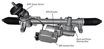
The EPS does this without taking up much space and without the use of hydraulic fluid. The steering rack and pinion gear assembly is not so different from traditional racks, but it does have a few extra components.

STEERING GEAR ASSEMBLY
The main components of this system are:
- Rack and pinion steering gear
- EPS control unit
- EPS actuator
- EPS torque sensor
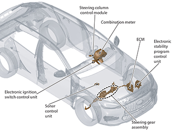
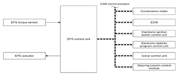
The components that play a role in the EPS system are:
- The COMBINATION METER mainly displays the EPS warning message signal when applicable.
- The ECM supplies the EPS with the engine speed signal.
- The ELECTRONIC IGNITION SWITCH CONTROL UNIT sends the:
- Ignition switch ON signal
- Battery voltage signal
- The ELECTRONIC STABILITY PROGRAM CONTROL UNIT transmits to the EPS control unit the following:
- Front LH and RH wheel speed signals
- Rear LH and RH wheel speed signals
- Steering assistance torque request signal
- Yaw rate signal
- Side G signal
- The SONAR CONTROL UNIT sends:
- Park assist status signal
- Steering angle command signal
- The STEERING COLUMN CONTROL MODULE transmits the steering angle sensor signal to the EPS control unit.
- The STEERING GEAR ASSEMBLY
QX30 ELECTRONIC POWER STEERING ASSIST FUNCTION
The STEERING ASSISTANCE FUNCTION can help provide steering torque in certain driving situations.
- The electronic stability program control unit and the EPS control unit communicate to help the driver:
- Counter or correct for oversteer
- With braking on various road surfaces
- The electronic stability program control unit senses the vehicle’s current status and when necessary:
- Steering assistance torque request signal is transmitted to the EPS control unit through the CAN.
REDUCING HOLDING-TORQUE FUNCTION STEERING ASSIST FUNCTION
- During a crosswind or on a road surface inclined on one side, the driver holds torque on the steering wheel in one direction to keep the vehicle in the center of the lane.
- The EPS control unit detects this holding torque.
- The EPS system compensates to help the driver maintain a holding torque.
- The amount of assistance the EPS provides to help the driver with holding torque depends on the vehicle speed.

To rule out incorrect compensation on a highway bend with a large radius, the EPS control unit receives these signals from the electronic stability program control unit:
- Yaw rate signal
- Sideways G force signal
OPERATION CONDITIONS
The EPS control unit requires the following to operate:
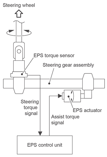
- Current steering movement from the EPS torque sensor.
- Current wheel speeds.
- Steering wheel angle and steering speed.
- Current engine speed.
- Ignition ON.
NOTE: The power steering is active when the ignition is switched ON, even if the engine is OFF.
EPS SYSTEM OPERATION SYSTEM DIAGRAM
EPS SYSTEM FAIL-SAFE
- When the EPS system is turned ON, the EPS control unit carries out a self-test. If a malfunction is detected, the EPS system is not switched ON, power steering assist is not operational and the system enters into a manual steering state.
- While driving, the EPS control unit checks the signals from the EPS torque sensor. If these signals are out of a predetermined range, the EPS system is turned OFF by the EPS control unit and an EPS warning message signal is sent to the combination meter and appears on the vehicle information display.
ADDITIONAL EPS SERVICE
Whenever adjusting the alignment or when removing or replacing the:
- EPS control unit
- Steering gear
- Steering column
Perform ALL of the following additional services:
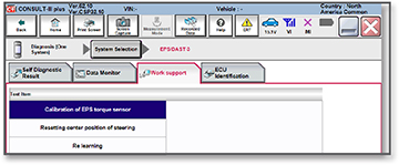
- Resetting center position of steering
- Reset coding of the EPS control unit
- Calibration of EPS torque sensor
- Re-learning with CONSULT-III plus
- Test drive
Refer to the Electronic Service Manual (ESM) for details on performing these services.

INTELLIGENT PARK ASSIST OPERATION
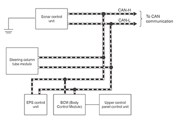
- The sonar control module calculates the required steering angle based on data from the EPS.
- The steering column tube module reads the data from the steering wheel angle sensor and sends information about the steering wheel angle via the CAN communication to the sonar control unit.
- The sonar control unit sends steering commands via CAN lines to the EPS control unit. The EPS control unit then operates the steering through the full range of motion from steering wheel lock-tolock as needed to park the vehicle.
- The EPS control unit sends information back to the sonar control unit on the CAN lines.
- The sonar control unit monitors the gear rack travel on the steering gear to calculate when and how much to turn the steering wheel to complete the parking assist function.
- The steering column tube module sends the angle information to the sonar control module through the CAN lines.
QX30 POWER STEERING with INTELLIGENT PARK ASSIST
The diagram visually represents the control modules used for the parking assist function.
STEERING WHEEL VIBRATION FOR LDW
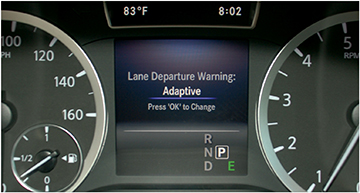
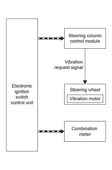
The steering wheel vibrates to help warn the driver that the vehicle is leaving the lane of travel during the LANE DEPARTURE WARNING (LDW) system operation. The part making the steering wheel vibrate is built into the steering wheel and is called a vibration motor.
The vibration motor is operated by the steering column control module. The steering column control module receives a signal from the front camera unit through the CAN lines.
NOTE: You may see the term “haptic” in the Service Manual. Haptic is the term used to describe the recreation of the sense of touch by applying forces, such as vibrations, or motions to the user.

The steering column control module then forwards the request over the steering LIN to the steering wheel electronics, which directly actuates the steering wheel vibration motor. The steering wheel vibration motor is actuated for a duration of 1.5 seconds.
The driver can configure the sensitivity of the LDW warnings in the Drivers Assistance menu which can affect the steering motor haptic vibration feel.
The operating modes available for selection are:
STANDARD – Sensitivity increased (warnings issued earlier and more frequently)
ADAPTIVE – Sensitivity reduced (warnings issued later and less often)
