2016 INFINITI Q50
2.0t ENGINE OVERVIEW
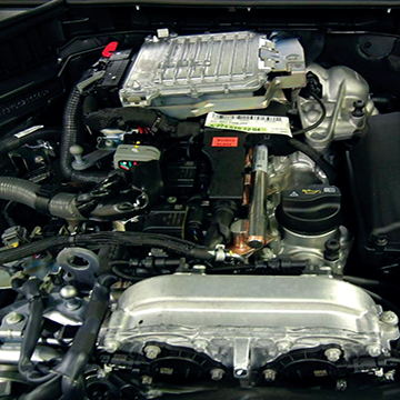
The 2016 Q50 2.0-LITER FOUR-CYLINDER TURBOCHARGED ENGINE produces 208 horsepower at 5,500 rpm with a peak torque of 258 lb-ft (350 Nm).
Displacement for this engine comes in at 1,991 cc. This in-line 4 with resin coated pistons and dual overhead cams, has a bore and stroke of 83x92 millimeters.
The compression ratio is 9.8:1 with 6,300 rpm as the maximum engine speed. The valve train includes four valves per cylinder with a variable valve timing system. Both the head and block are aluminum alloy and there are five main bearings.
2016 INFINITI Q50 2.0t ENGINE
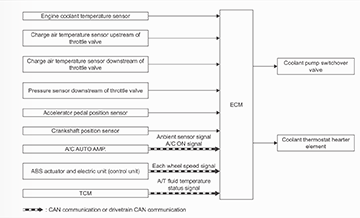
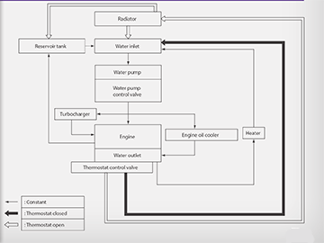
The THERMAL CONTROL SYSTEM performs four main cooling systems operations:
- Control after engine startup
- Coolant thermostat control
- Overheat protection function
- Cooling fan motor control
The system uses the ECM to control the:
- Coolant pump switchover valve
- Coolant thermostat heater element
- Engine cooling fan (not shown in this diagram)
The thermal control system function:
- Brings the engine up to operating tempreture faster.
- Helps the HVAC system provide heat to the passenger compartment faster.
- Helps improve fuel economy.
- Helps reduce harmful exhaust emissions.
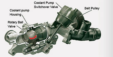
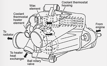
AS WE COVER THE THERMAL CONTROL SYSTEM, WE WILL DISCUSS THE OPERATION OF TWO ROTARY BALL VALVES:
- One is built into the coolant pump assembly. It is fully opened or fully closed using a vaccum actuator and the coolant pump switchover valve.
- The other ball valve is built into the coolant thermostat housing and is located on the opposite side of the engine from the coolant pump assembly. It is opened/closed using a wax element that is heated using the coolant tempreture and electrical heat (coolant thermostat heater element) via a signal from ECM.
CONTROL AFTER ENGINE STARTUP
After the engine starts, the ECM blocks coolant circulation to the cylinder head by closing the rotary ball valve in the coolant pump assembly.
The ECM does this by turning ON the coolant pump switchover valve. When the switchover valve is ON, vacuum is applied to the vacuum actuator pulling the rotary ball valve closed.
With the engine started and running, the ECM will keep the rotor ball valve closed to help heat the engine quickly until one or more of the following conditions are present:
- Coolant temperature is approximately 85°C (185°F) or above
- Charge air temperature is above the specified limit
- Engine speed is 4,000 rpm or more
- There is a heater request from the A/C auto amp (the coolant pump rotary ball valve must be open in order for coolant to flow to the heater core.
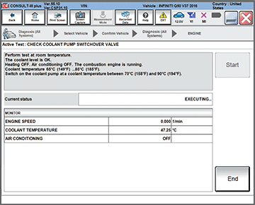
Note: C-III plus has an ACTIVE TEST to confirm the operation of coolant pump switchover valve. Notice the on-screen instructions indicate the test must be performed within a fairly narrow temperature range.
COOLANT THERMOSTAT CONTROL
The ECM controls the coolant thermostat heater element via a duty cycle signal. The duty cycle varies depending on the amount of opening desired of the rotary ball valve.
The COOLANT THERMOSTAT housing is located on the opposite side of the engine from the coolant pump assembly.
The wax element in the thermostat assembly expands and contracts based on coolant tempreature and/or thermostat heater element.
When the wax element expands and contracts, it opens and closes the rotary ball valve in the coolant thermostat housing.
COOLANT THERMOSTAT CONTROL (cont'd)
The thermostat ROTARY BALL VALVE IS CLOSED when:
- Coolant temperature is less than 95°C (203°F), and
- Coolant thermostat heater element is turned OFF by the ECM
In the closed position, coolant circulates in the engine, and to the heater core, if necessary, but not to the radiator.
The thermostat ROTARY BALL VALVE BEGINS TO OPEN when:
- Coolant temperature reaches approximately 98°C (208.4°F), or
- The ECM turns ON the heater element
The degree of opening changes depending on the amount of heat applied to the wax element.
In the partial open mode, some coolant is allowed to circulate to the radiator.
When the thermostat ROTARY BALL VALVE IS FULLY OPEN, the maximum amount of engine coolant is allowed to flow through the radiator.
When any one or more of the following conditions are present, the coolant temperature and/or the heater (via signal from the ECM) heats the wax element to fully open the rotary ball valve:
- Coolant temperature is approximately 108°C (226.4°F) or higher
- There is a full load (heavy throttle) and coolant temperature is 85°C (185°F) or more.
- Intake air temperature of 38°C (100.4°F) or more.
- Engine speeds of 3,000 rpm or more
- Engine load at 30% or more
COOLING FAN MOTOR CONTROL
The cooling fan motor operates on a Pulse Width Modulation signal from the ECM to the cooling fan control module:
- 10% turns the cooling fan motor OFF
- 20% operates the cooling fan motor at minimum speed
- 90% operates the cooling fan motor at maximum speed
The cooling fan motor operates at the maximum speed when abnormal signals occur.
COOLING FAN OPERATION AFTER IGNITION OFF
If coolant temperature or engine oil temperature is outside the threshold when the ignition is turned OFF, the fan motor is activated for 5 minutes at maximum. If the battery voltage level is too low, the fan motor is not activated.
CRANKCASE VENTILATION
The CRANKCASE VENTILATION SYSTEM on this vehicle does what all PCV systems do, it gets rid of excessive pressure (from combustion blowby) and gases in the crankcase. However, this system accomplishes that task a bit differently.
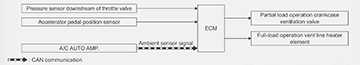
PARTIAL LOAD /NORMAL MODE
The PARTIAL LOAD OPERATION CRANKCASE VENTILATION VALVE is usually open and allows blowby gases to go from the oil separator to the boost air distributor pipe (intake manifold). During deceleration, the ECM closes the partial load crankcase ventilation valve to stop blow-by gas flow. Closing the valve at this time reduces engine noise during deceleration.
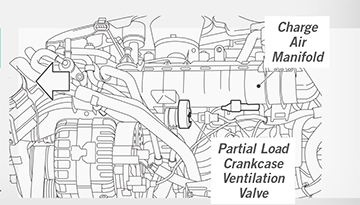
FULL LOAD MODE
Although the FULL-LOAD VENT LINE is always open – due to its location on the intake tube before the throttle valve - blow-by is not always flowing:
- When there is low to moderate throttle opening, there is little or no vacuum available to suck blow-by gases from the oil separator/crankcase.
- However, during full load operation (full throttle), enough vacuum is available at that location on the intake tube to assist in sucking blow-by gases from the oil separator.
Note: During full throttle, vacuum at the intake manifold is reduced, so the partial load valve will be less efficient. At the same time, full throttle increases blow-by. In this system, at full throttle, both vent lines are sucking blow-by from the crank case.
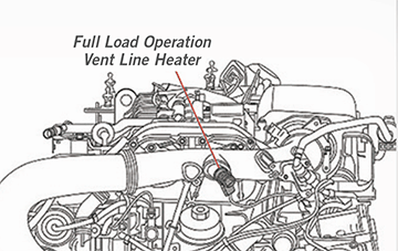
When the ambient temperature is less than approximately 7°C (44.6°F), the ECM turns ON the full-load operation vent line heater element.
Because vapor is not flowing constantly in the full load vent line; in cold weather vapor could freeze in the line and then be sucked into the engine if/ when heavy throttle is applied. Keeping this vent line heated in colder weather prevents frozen vapor from entering the engine intake and damaging the engine.
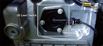
OIL LEVEL SENSOR (a.k.a. oil level switch)
Depending on which section of
the ESM you are reading, you may
find this described as an Oil Level
Sensor or an Oil Level Switch. The
EC section uses both terms.
When the engine oil level is low, a
signal from the oil level sensor is
used to turn ON the Low
Oil Level message in the
vehicle information display.

Note: The Q50 2.0L is not equipped with an oil pressure sensor or an oil pressure warning light.
ENGINE OIL COOLER
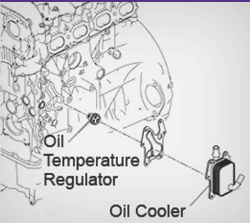
The engine Oil Cooler is used to transfer engine oil heat from the engine oil to the engine coolant.
The Oil Temperature Regulator is a thermovalve that allows engine oil to enter the cooler after a certain temperature is reached.
The oil cooler transfers heat from the crankcase oil to the engine coolant to help prevent oil degradation due to thermal breakdown.
CYLINDER HEAD COVER
The CYLINDER HEAD COVER (more commonly known as the rocker cover or valve cover) incorporates the top half of the camshaft bearings. The cylinder head cover does not have cam bearing inserts.
The cams ride on oil pressure contained by the cylinder head cover. The cylinder head cover and cylinder head cannot be replaced separately. If replacement is needed, they are both replaced as one part.
Use extra care when dealing with the camshafts or the cover.
Removing or reinstalling the camshafts requires a Special Tool Camshaft Holding Device J-51931. It holds both camshafts prior to removing the camshaft adjusters.
HYDRAULIC LIFTERS AND ROCKER ARMS
ROCKER ARM AND HYDRAULIC VALVE CLEARANCE ADJUSTMENT ELEMENT
The rocker arms and clearance adjustment elements reduce engine friction and extend camshaft lobe life. It is critical to place these back in the same position if they are removed for any reason.
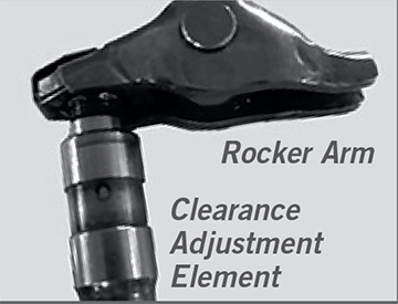
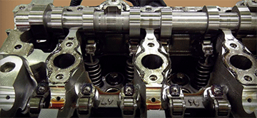
The HYDRAULIC LIFTERS keep the valves adjusted properly without routine mechanical valve adjustments. The Q50 ESM refers to them as hydraulic valve clearance adjustment elements.
As with all hydraulic lifters, be sure to place them back in the same holes if you remove them for any reason.
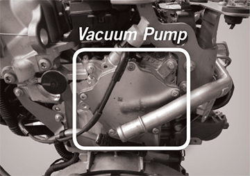
CAMSHAFT DRIVEN VACUUM PUMP
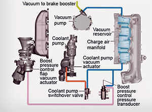
This device supplies the necessary
vacuum to the vacuum reservoir
and the brake booster.
The vacuum reservoir maintains
proper operation of vacuum
operated components, such as:
- Coolant pump vacuum actuator that operates the rotary ball valve
- Boost pressure control flap vacuum actuator
The VACUUM PUMP mounts to the rear of the engine and is driven by the EXHAUST CAMSHAFT.
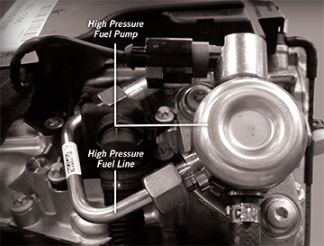
CAMSHAFT DRIVEN HIGH PRESSURE FUEL PUMP
- The high pressure fuel pump receives fuel from the intank pump, increases the pressure, and delivers the high pressure fuel to the fuel rail.
- The ECM uses the quantity control valve to control the fuel pressure.
- Fuel pressure ranges from 2900 psi to 3915 psi.
- The high pressure fuel pump also includes a damper to help control pressure fluctuation.