IDLE STOP SYSTEM
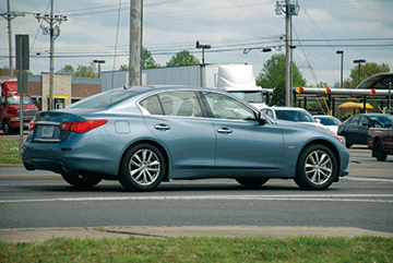
The 2016 Q50 2.0L Turbo Gasoline Engine can be equipped with engine idle stop start technology. You likely have heard of this, but this may be the first time you have the opportunity to work on this type of system. This article is intended to give an introduction of this system, but does not contain all system details. As usual, the Electronic Service Manual (ESM) contains all the information (components, wiring, system operation, CONSULT-III plus diagnostic, etc.).
During normal vehicle operation with the gear selector in Drive, the basic function of this system is simple;
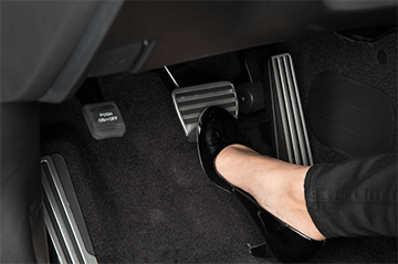
- Automatically turns the engine OFF (stops the engine) when the vehicle is stopped.
- Automatically turns the engine ON (starts the engine) when the driver releases the brake pedal.
This table shows the basic operation – but remember – this is just the basics. There are many other variables that the ECM uses to calculate the operation of the Idle Stop/Start system.
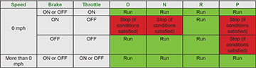
Although the basic function may be simple, many vehicle systems must be monitored; and the control units involved
must perform extensive calculations to make the Idle Stop/Start system function smoothly.
The following tables give the Start Stop Function Readiness Conditions, Engine Stop Conditions, and Engine
Start Conditions. Reviewing these tables will give you an understanding of the many inputs, condition, and
calculations required for the Idle Stop/Start system operation.
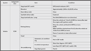
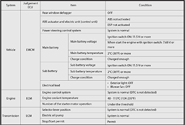
Start Stop Function Readiness Conditions
The ECM judges that Idle Stop/Start function is ready when the following conditions are satisfied:
Engine Stop Conditions
When all of the following conditions are satisfied, the ECM stops the engine.
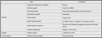
* EMCM calculates a brake pedal status based on the brake pedal position switch signal and the brake fluid pressure sensor signal. And then, EMCM transmits a brake pedal position signal to ECM via CAN communication.
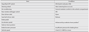
Engine Restart Conditions
When any one or more of the following conditions is satisfied, the ECM restarts the engine:
* For details refer to the 2016 Q50 ESM section EC4 Engine Control System.
As you can see from the lists and the tables the variables for the Idle Stop/Start system operation are many, such that:
- The engine will not always stop when the vehicle is stopped.
- Sometimes the engine will restart before the driver releases the brake pedal.
Below are some of the common conditions for stop/start operation.
The Idle Stop/Start system will not stop the engine when:
- Vehicle has not been driven (idle only) after start up
- Accelerator pedal is depressed
- Steering wheel is operated or wheels are not pointed straight ahead
- Engine coolant temperature is low
- Temperature inside the vehicle is lower than 68° F (20°C) or higher than 86° F (30°C)
- Front or rear defroster is ON
- HVAC fan speed is at maximum
- Battery capacity is low or discharged
- Driver’s seat belt is not fastened
- When stopping the vehicle on steep sloping roads
Note: (This is not a complete list – see Owner’s Manual and ESM).
The Idle Stop/Start system will restart the engine when:
- Vehicle moves at 1.3 mph or more
- An electrical power supply is detected (such as a battery charger or jumper cables)
- High load accessory is turned ON
- Front or rear defroster is turned ON
- Driver’s foot is relaxed on the brake pedal (brake pedal pressure is reduced to below the specified amount)
- Shift lever is moved to Reverse
- Steering wheel is turned
- More than 3 minutes have passed
Note: (This is not a complete list – see Owner’s Manual and ESM).
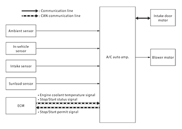
A/C Operation and Idle Stop/Start
When the engine stops, the A/C compressor is not operating, cool air will be diminished; especially if it’s hot outside. Cabin comfort is important, so signals from the A/C system are used as one of the determining factors in Idle Stop/ Start operation.
If the various signals from the A/C system indicate the cabin comfort can be maintained with the engine OFF, then the Idle Stop/Start system will be allowed to stop the engine, as long as all other factors are satisfied.
- When the A/C auto amp. recognizes that the Idle Stop/Start system is operating (engine is stopped), it changes control characteristics of air flow and air inlet within a range that does not adversely affect the comfort level. This helps prolong stop/start operation time.
- When the A/C auto amp. judges that the comfort level in the passenger room cannot be maintained while the engine is stopped, it cancels the Stop/Start permit signal and requests the ECM to restart the engine.
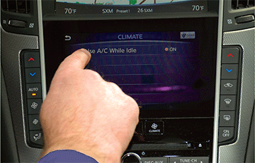
- Using the “Use A/C While Idle” option under Settings > Other > CLIMATE will affect the A/C operation as follows:
- When turned OFF and the Idle Stop/Start system has stopped the engine, the HVAC system will operate as described on the previous page.
- When turned ON and the Idle Stop/Start system has stopped the engine, the A/C system operation will not be changed. It will continue to operate as it did when the engine is running. But, in order to keep the cabin comfort unchanged, the Idle Stop/Start system will stop the engine less often when this option is set to ON.
Engine Start vs Engine Restart by Idle Stop System
The following starter circuit diagrams show the difference between the engine start with the ignition switch, and engine re-start by the Idle Stop/Start system:
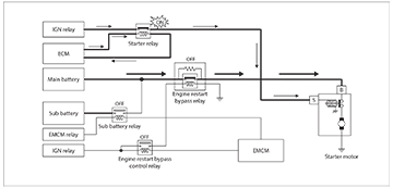
Engine Start with Ignition Switch:
During Engine Restart by Stop/Start System
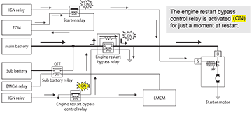
- The ECM turns ON the starter relay.
- At the same time the EMCM turns ON (for just a moment) the engine restart bypass control relay which activates the engine restart bypass relay for just a moment.
- When the starter motor begins rotating, the EMCM turns OFF the engine restart bypass control relay which deactivates the engine restart bypass relay.
Engine Restart Bypass Relay
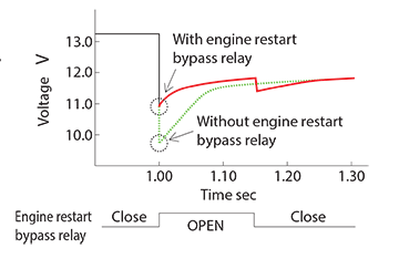
The switch in this relay is normally closed allowing voltage to pass directly through the switch to the starter motor, as shown in the diagram for During Engine Start with Ignition Switch. For the Idle Stop/Start system, this relay is used to stabilize battery voltage during engine restarts and reduce main battery degradation as follows:
- When a restart occurs, the engine restart bypass relay is activated, for just a moment.
- The switch inside the relay is opened, for just a moment. Voltage going to the starter is directed through the resistance circuit inside the relay, for just a moment.
- This momentary direction of the voltage through the resistance circuit reduces the battery voltage drop that occurs just as the starter motor begins to rotate.
- The relay switch is open for just a moment and then closed. Voltage then passes directly to the starter motor while it is rotating.
Sub Battery Relay
While the engine is running, the sub battery relay is ON, connecting the main battery and sub battery, allowing generated power to flow to all systems and charge both batteries.
When a re-start occurs:
- The EMCM turns OFF the sub battery relay, disconnecting the sub-battery from the main battery.
- Only the main battery supplies power to the starter motor. The restart will cause a voltage drop in the main battery.
- The sub battery is isolated from the restart voltage drop. Full voltage is available to vehicle system connected to the sub battery. These systems are protected from the impact of a restart (such as a memory reset) due to reduced voltage supply.
Other Equipment That Supports the Idle Stop/ Start System
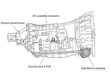
A/T Sub-electric Pump
The transmission is equipped with a Sub-electric oil pump to keep the transmission supplied with ATF pressure when the engine is automatically turned OFF by the Idle Stop/Start system.
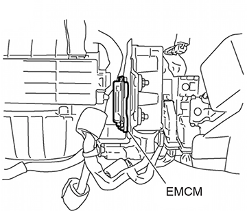
Energy Management Control Module (EMCM)
Located behind the glove box on the A pillar, its responsibilities include:
- Main and sub battery charge state monitoring
- Sub battery isolation for the Idle Stop/Start system engine restart process.
- Feedback of brake system information for Idle Stop/ Start system control (it uses inputs from the brake system to provide brake status to the ECM)
- Alternator regeneration (battery recharge) management.
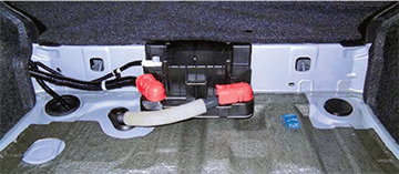
Sub Battery
The sub battery is located in the trunk. Its main function
is to support the Idle Stop/Start system. The sub-battery
maintains accessory power during restart.
The sub battery and the main battery must be designed
for use with an Idle Stop/Start system.
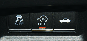
Idle Stop OFF Switch
The Idle Stop OFF switch is mounted on the switch
panel of the driver side lower instrument panel.
When the Idle Stop OFF switch is pressed, the
indicator light turns ON and the Idle Stop/Start
system is deactivated.
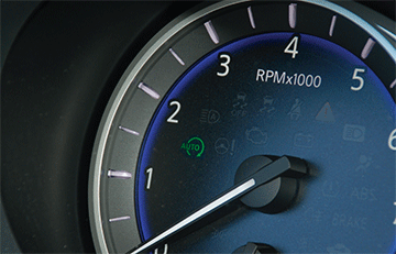
Idle Stop Indicator Light The Idle Stop indicator light informs the driver of the status of the Idle Stop/Start system:
- Turns ON while the Idle Stop/Start system is operating (engine stopped).
- Blinks at low speed when a malfunction related to the Idle Stop/Start system is detected.
- Blinks at high speed and sounds the warning buzzer when the driver′s operation is judged as improper operation while the Idle Stop/Start system is operating.
- After restarting the engine, the Idle Stop indicator light turns OFF.
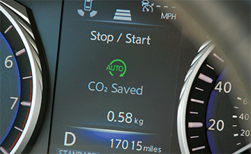
Information Display
While the engine is stopped by the Idle Stop/Start
system this information will be shown on the information
display:
- Engine stopped time
- Amount of CO2 saved by the Idle Stop/Start system
Retrograde Movement Control Function
- This system is active when the Idle Stop/Start system is active.
- This system reduces the backwards movement of the vehicle that may occur, when stopped on a hill, between releasing the brake pedal and pressing the accelerator pedal.
- ABS system brake application is used to reduce the backwards movement.