QX30 PARKING SENSOR SYSTEM
The parking sensor system is an electronic parking aid that uses ultrasonic sensors for a measuring procedure that records a distance value between the vehicle and an obstacle. On the basis of the distance values determined in this way, the system warns the driver with visual and audible signals to help them avoid stationary obstacles while parking or while maneuvering the vehicle in a small area.
OVERVIEW
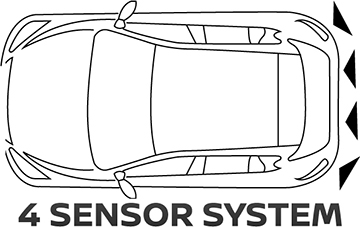
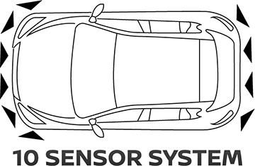
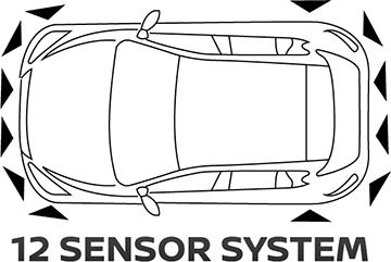
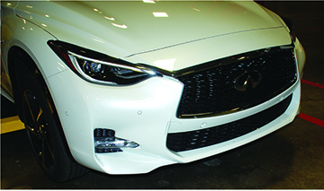
The parking sensor system comes in several different configurations of parking sensors fitted to the front and rear bumpers depending on how the vehicle is equipped. Some vehicles have 4 sensors, some have 10 sensors, and still others have 12 sensors.
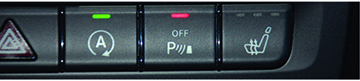
The parking sensor system is deactivated by the Parking Sensor System OFF switch. The switch allows the driver to turn ON/OFF the parking sensor system when it is pushed. The red LED indicator light on the switch illuminates when the system is turned OFF.
![]()
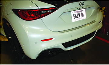
- Small objects below the bumper or objects that are too close to the bumper might not be detected.
- Since the sensors are located on the front and rear fascia, any damage to the fascia will cause inaccurate operation.
NOTE: The parking sensor system will turn ON automatically when the ignition switch is turned from the OFF position to the ON position.

Possible Sensor Configurations
- The 4 sensor system has sensors only in the rear fascia and operates when the shift lever is in R (Reverse).
- The 10 sensor system has 4 sensors in the rear fascia and 6 sensors in the front fascia. The 12 sensor system has 6 sensors in the front fascia and 6 sensors in the rear fascia. These systems indicate obstacles in the front when the shift lever is in D (Drive). When the shift lever is in R (Reverse), they indicate obstacles in the front and rear of the vehicle.
NOTE: The 4 sensor system warns the driver about rear obstacles with visual and audible signals when the shift lever is in the R (Reverse) position.
NOTE: Vehicles equipped with front and rear sensors:
- provide visual and audible signals for front only when the shift lever is in the D (Drive) position.
- provide visual and audible signals for both front and rear obstacles when the shift lever is in the R (Reverse) position.

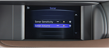
Parking Sensor Function Settings
The parking sensor settings can be changed in the vehicle using the following procedure:
1. Press the <MENU> button and touch the [Settings] icon on the vehicle information display.
2. Touch [Camera/Sonar].
3. Touch [Sonar].
Sonar Sensitivity:
Adjust the parking sensor sensitivity by touching [+]/[-].
Sonar Volume:
Adjust the warning tone volume by touching [+]/[-].
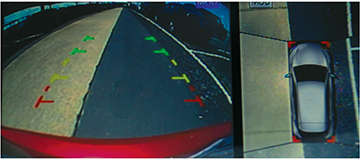
Sonar Visual Indicators
- Sonar visual indicators are displayed in the center display of the RearView or Around View® Monitor. It’s also on the Bird’s-Eye view.
- The sonar control unit displays a warning on the sonar indicator in three stages (green, yellow, and red) according to the distance from an obstacle.
Sensor System Operation
- When an object is detected, the indicator (green) appears and blinks and the tone sounds intermittently with audio tones emitting from the vehicle speaker nearest the area where the detected object is located. When the vehicle moves closer to the object, the color of the indicator turns yellow and the rate of the blinking increases and the tone sound frequency increases. When the vehicle is very close to the object, the indicator stops blinking and turns red and the tone sounds continuously.
Sensor System Operation (continued)
- The parking sensor system deactivates at speeds above 10 MPH (16 kph) and reactivates when the vehicle speed drops below 10 MPH (16 kph).
- The system also deactivates once an electrical connection is established between the vehicle and a trailer. When a trailer is attached, IPA is not available.
- When the parking sensors are dirty or there is interference from random radio waves or ultrasound waves, the red segments light up and then the system deactivates. If this occurs, cleaning the sensors or changing the vehicle’s location should resolve the incident.
If a malfunction or system error occurs, the sonar system is deactivated and the LED on the sonar system switch in the upper control panel control unit illuminates.
A system error can have the following causes:
- Malfunctioning component
- Error in communication
- Over-voltage or under-voltage
System Diagram
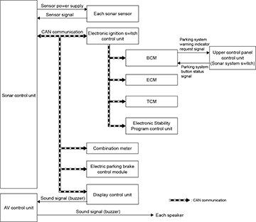
SONAR Control Unit Input and Output Signals
Input Signals
- ECM and TCM
- Gear status signal
- BCM
- Parking system button status signal
- Dusk setting signal
- Electronic ignition switch control unit
- Circuit 15 status ON signal
- Electronic Stability Program control unit
- Wheel rotation direction signal
- Wheel speed signal
- Combination meter
- Vehicle speed signal
- Parking system status signal
- Electric parking brake control module
- Parking brake status signal
Output Signals
- BCM
- Parking system status indicator request signal
- Display control unit
- Sonar indicator display signal
- Buzzer output signal
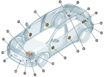
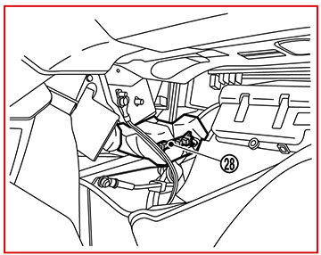
Component location
No. Component
1 Rear door speaker RH
2 Front door speaker RH
3 ECM
4 Side sensor front RH
5 Corner sensor front RH
6 Center sensor front RH
7 Center sensor front LH
8 Corner sensor front LH
9 TCM
10 Side sensor front LH
11 Electronic Stability Program control unit
12 Front door speaker LH
13 Rear door speaker LH
14 Electric parking brake control module
15 Around View® Monitor control unit
16 Side sensor rear LH
17 Corner sensor rear LH
18 Center sensor rear LH
19 Center sensor rear RH
20 Corner sensor rear RH
21 Side sensor rear RH
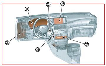
Component location
No. Component
22 Display control unit
23 Electronic ignition switch control unit
24 Combination meter
25 BCM
26 AV control unit
27 Upper control panel control unit (sonar system switch)
28 Sonar control unit
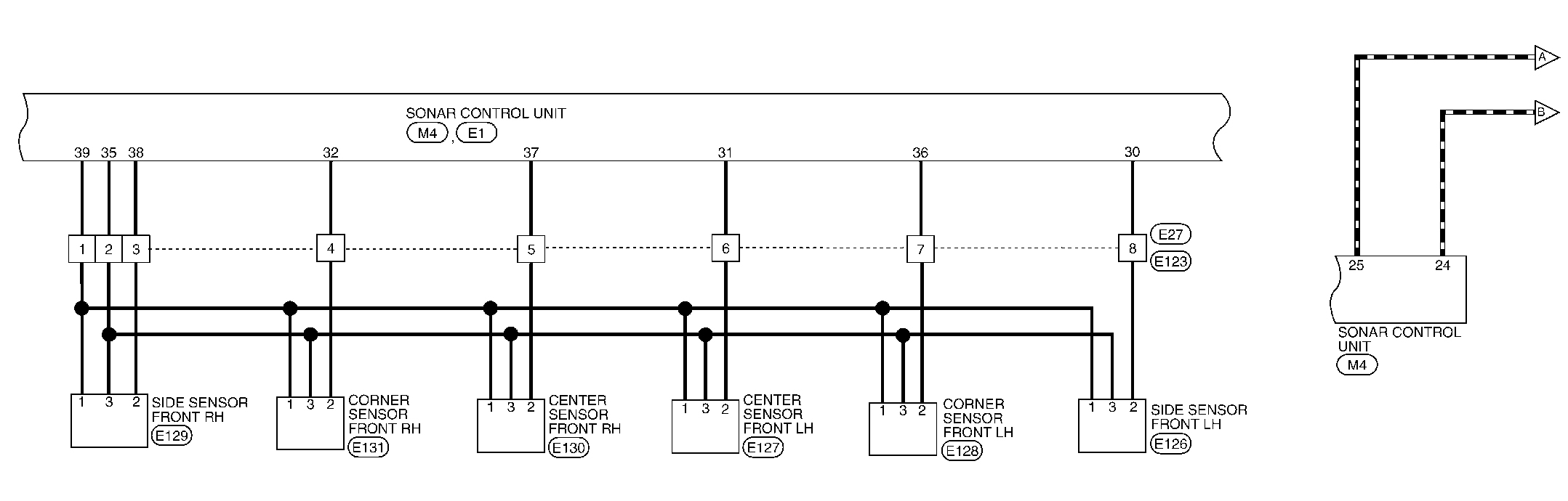
Circuit diagram - SONAR SYSTEM (REAR 6 SENSORS WITH PARK ASSIST)
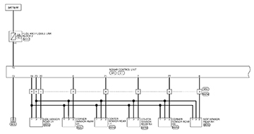
Circuit diagram - SONAR SYSTEM (FRONT 6 SENSORS WITH PARK ASSIST)