QX30 POTENTIAL DISTRIBUTION ELECTRICAL CONNECTOR (PDEC)
PDEC, what is it? What is it used for?
As with most modern vehicles, the QX30 uses many Electronic Control Units (ECU) which are constantly communicating with each other by transmitting and receiving signals that are relevant to their particular functions.
The communication system used by the ECUs is referred to as the LAN (Local Area Network) system. The LAN consists of:
- Controller Area Network (CAN)
- Local Interconnect Network (LIN)
CAN Potential Distributor Electrical Connector (PDEC)
In CAN communication, control units are connected with two communication lines (CAN-H, CAN-L), which allows a high rate of information transmission with less wiring. Each control unit transmits/receives data but selectively reads required data only.
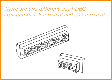
Each ECU connects to a CAN Potential Distributor Electrical Connector (PDEC). The PDEC contains a bridging resistor between CAN-H and CAN-L, which creates the potential difference required for communication transmission.
- The bridging resistors are located in the PDEC connectors.
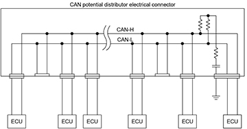
System Diagram
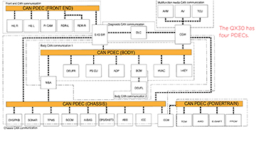
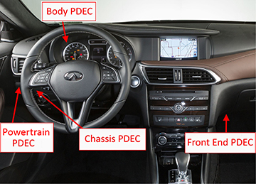
Where the PDECs are located
How to use the PDEC connectors for diagnosis
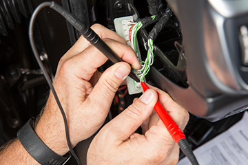
When an error occurs in a CAN line, you may need to remove a PDEC connector to check the resistance. This may help you to isolate the possible source for the error on the CAN line.
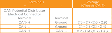
Resistance between CAN-H and CAN-L terminals can be checked.

Operating voltages for each CAN bus are different at IGN-ON condition. (Refer to the ESM for details.)
Conclusions/diagnostics that can be gained from using it.
In the CAN communication system, multiple control units mutually transmit and receive signals. If an error occurs on a CAN, several control units may malfunction or go into fail-safe mode at the same time. Looking at the system diagram, you may be able to see what PDEC group or common point might have a problem that would cause multiple controllers to malfunction or go into safe-mode.
CONSULT-III plus can help you to extract the possible root causes by checking the:
- Response to the system call
- Control unit diagnosis information
- Self-diagnosis
- CAN diagnostic support monitor
If communication signals cannot be transmitted or received among control units communicating via the CAN communication line, a CAN communication-related DTC is displayed on the CONSULT “Self Diagnostic Result” screen.
Even when the CAN system is normal, you may still get a CAN DTC under the following conditions:
- If a CAN communication signal is not transmitted or received between units for 2 seconds or more.
- When removing and installing a CAN communication unit and related parts while turning the ignition switch ON.
- Remember that a blown or removed fuse will make the corresponding control unit stop communicating on the CAN.
- Errors may also be detected if the power supply circuit to a control unit malfunctions.
- Depending on the control unit, a voltage drop while turning on the ignition with a discharged battery could cause an error.
- If reprogramming a module does not complete normally, you may get a CAN DTC.
NOTE: When the SELF-DIAG RESULTS shows a CAN communication trouble code, it does not necessarily mean there is trouble with the CAN line. For example, if you just replaced a module or a blown fuse, or even just recharged a dead battery and then turn the ignition ON, you could get a CAN DTC. Erase the self-diagnosis memory of each control unit and then retest.
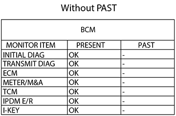
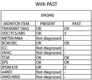
Here is an example of what you might see on CONSULT when you display the CAN Diagnosis Support Monitor.
- The number indicates the number of ignition switch cycles from OFF to ON.
- OK means that the item is normal or OK at present.
- Not diagnosed means that the diagnosis was not performed on that unit.