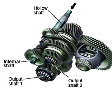
The GE7F30A TRANSMISSION includes two sub-transaxles. In other words, this transmission has an internal shaft and a hollow shaft for power input, with two output shafts all encased in one housing.
Power flows for gears 1, 2, 4, and 5 on sub-transaxle 1.
Power for gears 3, 6, 7, and reverse flows through sub-transaxle 2.
Power is transmitted through only one of these sub-transaxles at a time.
MAIN COMPONENTS
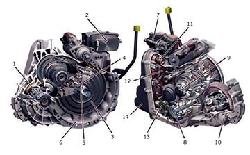
1. Differential Pinion
2. Oil Heat Exchanger
3. Dual Clutch
4. Hollow Shaft
5. Internal Shaft
6. Clutch Housing
7. Oil Filter
8. Output Shaft 1
9. Output Shaft 2
10. Transmission Housing
11. TCM Electrical Connector
12. TCM
13. Park Pawl System
14. Oil Pan
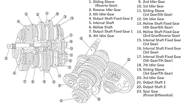
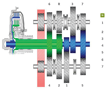
GEAR SET
GEAR POWER FLOW NEUTRAL
Neither K1 nor K2 clutches are engaged.
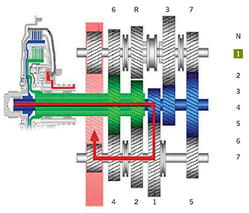
FIRST GEAR
K1 clutch is engaged.
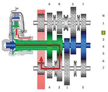
SECOND GEAR
K2 clutch is engaged.
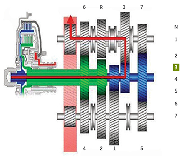
THIRD GEAR
K1 clutch is engaged.
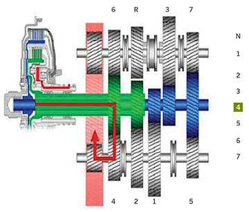
FOURTH GEAR
K2 clutch is engaged.
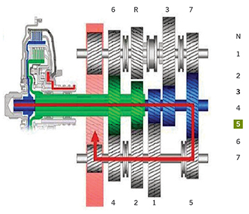
FIFTH GEAR
K1 clutch is engaged.
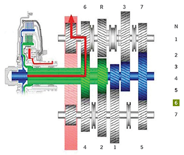
SIXTH GEAR
K2 clutch is engaged.
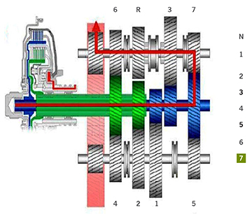
SEVENTH GEAR
K1 clutch is engaged.
REVERSE
K2 clutch is engaged. Reverse gear is driven by the gear wheel for 2nd gear on the opposite output shaft.
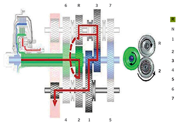
POWER FLOW IS:
- Hollow input shaft to the 2nd gear wheel via the fixed gear
- Gear wheel 2 transmits the power to the reverse gear.
- The reverse gear is permanently connected to the synchronizer body of the right gear shift sleeve so that it is frictionally connected to the adjacent gear wheel for 3rd gear.
- Gear wheel 3 transmits the power via the two fixed gears on drive shaft 1 to the gear wheel of 1st gear. Via the right gear shift sleeve, gear wheel 1 is frictionally connected to output shaft 1.
- The driving power is transmitted via the fixed gear of output shaft 1 to the differential, which then turns in the opposite direction as the other gears.
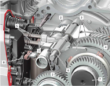
GEAR SHIFT OPERATION
To change gears, oil pressure acts upon the gear positioning cylinder to move the shift fork.
Permanent magnets are imbedded in the shift forks so that the TCM knows the shift fork position.
1. Permanent Magnet
2. Gear Positioning Cylinder
3. Shift Fork
4. Sliding Sleeve of the Synchronization System
5. Oil Pipe
6. Shift Rod
7. Output Shaft 2
8. Shift Fork Position Sensor 3
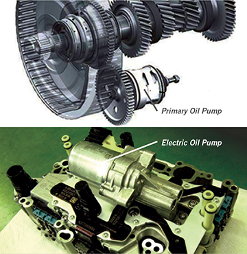
TRANSMISSION OIL PUMPS
GE7F30A oil supply and lubrication occur through TWO TRANSMISSION OIL PUMPS that deliver oil pressure independently of each other:
- The PRIMARY pump
- The ELECTRIC pump
The PRIMARY OIL PUMP is mechanical and provides an oil supply whenever the engine is running. The pump pressure is regulated between 50 to 320 PSI (350 to 2200 kPa) depending on engine speed.
The ELECTRIC OIL PUMP supports the primary pump under the following operating conditions:
- At low rotational speeds
- In start/stop mode
- High automatic transmission fluid temperature to assist in clutch cooling
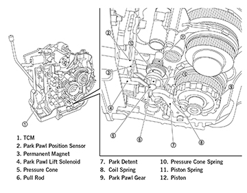
The PARK PAWL is not engaged by the driver with a mechanical cable or linkage connection. In order to change the park pawl position, the TCM actuates the lift solenoid, which presses the locking pin out of the catch of the piston. The piston is then pressurized on one side with hydraulic pressure. The TCM energizes the park pawl switchover valve to allow hydraulic flow to the corresponding pressure chamber for piston actuation.
DISENGAGE PARK PAWL
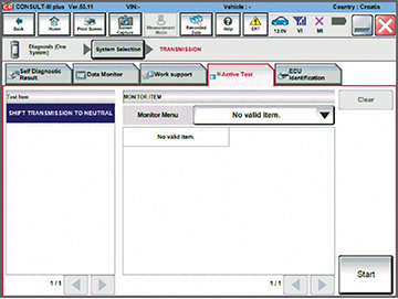
If there is a malfunction or low battery or power loss, the park pawl can be released using C-III plus.
Of course, C-III plus won’t work unless the vehicle has power. In the case of a power loss (dead battery), an external power supply is needed to jump the battery, then connect C-III plus and use Active Test to run the transmission electrical pump (creating hydraulic pressure). This will then allow C-III plus to disengage the park pawl.
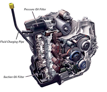
OIL LEVEL CHECK AND FILTERS
There are two oil filters: An External Pressure Oil Filter and a Suction Oil Filter located in the oil sump. Replace both oil filters at the 60,000 mile transmission oil change interval.
Oil level check is only possible using CONSULT-III plus. You’ll also need the special service tool J-51940 oil level dipstick. On CONSULT-III plus select “TRANSMISSION”, “Work Support”, and “Oil level check” Follow the C-III plus on screen instructions to perform the oil level check.
Was this article helpful? We value your opinion! Email us at TechTalk@nissan-usa.com.